The Manual J form is an essential tool for anyone involved in the design and installation of heating, ventilation, and air conditioning (HVAC) systems, particularly in residential settings. This form serves as a comprehensive worksheet that captures critical data necessary for accurately calculating the heating and cooling loads of a home. It emphasizes the importance of conducting load calculations on a room-by-room basis, which is vital for effective duct sizing and overall system efficiency. Designed specifically for homes built in Utah's dry climate, the Manual J form includes sections for entering design conditions such as outside and inside temperatures, as well as the specific construction quality of the home. In addition, it requires detailed information about the heating and cooling equipment being used, including manufacturer specifications and performance ratings. The form also addresses factors like infiltration, latent gains, and sensible heat ratios, all of which play a significant role in determining the appropriate HVAC system size. By ensuring that all relevant data is meticulously recorded and justified, the Manual J form helps professionals create HVAC systems that are not only efficient but also tailored to the unique needs of each residence.

Building Services & Civil Enforcement slcpermits.com
451 South State Street, Room 215 |
PO Box 145490 |
Salt Lake City, Utah 84111 |
Salt Lake City, Utah |
Office only |
Updated 12/2012 |
BLD # Received by
Date Valuation
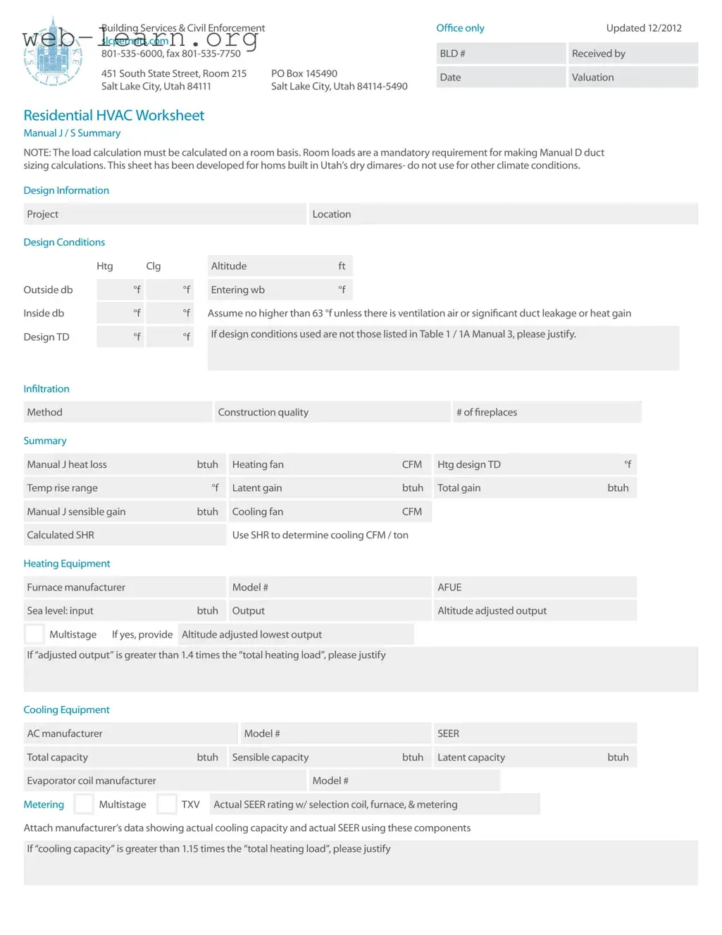
Residential HVAC Worksheet
Manual J / S Summary
NOTE: The load calculation must be calculated on a room basis. Room loads are a mandatory requirement for making Manual D duct sizing calculations. This sheet has been developed for homs built in Utah’s dry dimares- do not use for other climate conditions.
Design Information |
|
|
|
|
|
|
|
|
|
|
|
|
|
|
|
|
|
|
|
|
|
|
|
|
|
|||||
|
|
|
|
|
|
|
|
|
|
|
|
|
|
|
|
|
|
|
|
|
|
|
|
|
|
|
|
|
|
|
|
Project |
|
|
|
|
|
|
|
|
|
|
|
|
|
|
Location |
|
|
|
|
|
|
|
|
|
|
|
|||
|
|
|
|
|
|
|
|
|
|
|
|
|
|
|
|
|
|
|
|
|
|
|
|
|
|
|
|
|
|
|
Design Conditions |
|
|
|
|
|
|
|
|
|
|
|
|
|
|
|
|
|
|
|
|
|
|
|
|
|
|||||
|
|
|
|
|
|
|
|
|
|
|
|
|
|
|
|
|
|
|
|
|
|
|
|
|
|
|
|
|
||
|
|
Htg |
Clg |
|
|
Altitude |
|
|
ft |
|
|
|
|
|
|
|
|
|
|
|
|
|
||||||||
|
|
|
|
|
|
|
|
|
|
|
|
|
|
|
|
|
|
|
|
|
|
|
|
|
|
|
|
|
|
|
|
|
|
|
|
|
|
|
|
|
|
|
|
|
|
|
|
|
|
|
|
|
|
|
|
|
|
|
|||
Outside db |
|
|
°f |
|
|
°f |
|
Entering wb |
|
|
°f |
|
|
|
|
|
|
|
|
|
|
|
|
|
||||||
|
|
|
|
|
|
|
|
|
|
|
|
|
|
|
|
|
|
|
|
|
|
|
|
|
|
|
|
|
||
|
|
|
|
|
|
|
|
|
|
|
|
|
|
|
|
|
||||||||||||||
Inside db |
|
|
°f |
|
|
°f |
|
Assume no higher than 63 °f unless there is ventilation air or significant duct leakage or heat gain |
||||||||||||||||||||||
|
|
|
|
|
|
|
|
|
|
|
|
|
|
|
|
|
|
|
|
|
|
|
|
|
|
|
|
|||
|
|
|
|
|
|
|
|
|
|
|
|
|
|
|
|
|
|
|
|
|
|
|
|
|
|
|
|
|
|
|
Design TD |
|
|
°f |
|
|
°f |
|
If design conditions used are not those listed in Table 1 / 1A Manual 3, please justify. |
|
|
|
|
||||||||||||||||||
|
|
|
|
|
|
|
|
|
|
|
|
|
|
|
|
|
|
|
|
|
|
|
|
|
|
|
||||
|
|
|
|
|
|
|
|
|
|
|
|
|
|
|
|
|
|
|
|
|
|
|
|
|
|
|
|
|
|
|
Infiltration |
|
|
|
|
|
|
|
|
|
|
|
|
|
|
|
|
|
|
|
|
|
|
|
|
|
|
|
|
|
|
|
|
|
|
|
|
|
|
|
|
|
|
|
|
|
|
|
|
|
|
|
|
|
|
|
|
|
|
|
||
|
|
|
|
|
|
|
|
|
|
|
|
|
|
|
|
|
|
|
|
|
|
|
|
|
|
|
|
|
|
|
|
Method |
|
|
|
|
|
|
|
|
Construction quality |
|
|
|
|
|
|
|
|
# of fireplaces |
|
|
|
|
|
||||||
|
|
|
|
|
|
|
|
|
|
|
|
|
|
|
|
|
|
|
|
|
|
|
|
|
|
|
|
|
|
|
Summary |
|
|
|
|
|
|
|
|
|
|
|
|
|
|
|
|
|
|
|
|
|
|
|
|
|
|
|
|
|
|
|
|
|
|
|
|
|
|
|
|
|
|
|
|
|
|
|
|
|
|
|
|
|
|
|
|
|
||||
|
Manual J heat loss |
|
|
|
|
btuh |
|
Heating fan |
|
|
|
|
CFM |
|
Htg design TD |
|
°f |
|
|
|
||||||||||
|
|
|
|
|
|
|
|
|
|
|
|
|
|
|
|
|
|
|
|
|
|
|
|
|
|
|
|
|||
|
|
|
|
|
|
|
|
|
|
|
|
|
|
|
|
|
|
|
|
|
|
|
|
|
|
|
|
|||
|
Temp rise range |
|
|
|
|
to |
|
|
°f |
|
Latent gain |
|
|
|
|
btuh |
|
Total gain |
|
|
btuh |
|
|
|
||||||
|
|
|
|
|
|
|
|
|
|
|
|
|
|
|
|
|
|
|
|
|
|
|
|
|
|
|
|
|
||
|
|
|
|
|
|
|
|
|
|
|
|
|
|
|
|
|
|
|
|
|
|
|
|
|
|
|
|
|
||
|
Manual J sensible gain |
|
|
|
btuh |
|
Cooling fan |
|
|
|
|
CFM |
|
|
|
|
|
|
|
|
|
|
||||||||
|
|
|
|
|
|
|
|
|
|
|
|
|
|
|
|
|
|
|
|
|
|
|
|
|
|
|
|
|
|
|
|
|
|
|
|
|
|
|
|
|
|
|
Use SHR to determine cooling CFM / ton |
|
|
|
|
|
|
|
|
|
|
||||||||
|
Calculated SHR |
|
|
|
|
|
|
|
|
|
|
|
|
|
|
|
|
|
|
|
|
|||||||||
|
|
|
|
|
|
|
|
|
|
|
|
|
|
|
|
|
|
|
|
|
|
|
|
|
|
|
|
|
|
|
Heating Equipment |
|
|
|
|
|
|
|
|
|
|
|
|
|
|
|
|
|
|
|
|
|
|
|
|
|
|||||
|
|
|
|
|
|
|
|
|
|
|
|
|
|
|
|
|
|
|
|
|
|
|
|
|
|
|
|
|||
|
Furnace manufacturer |
|
|
|
|
|
|
|
Model # |
|
|
|
|
|
|
|
AFUE |
|
|
|
|
|
|
|||||||
|
|
|
|
|
|
|
|
|
|
|
|
|
|
|
|
|
|
|
|
|
|
|
|
|
|
|
|
|||
|
|
|
|
|
|
|
|
|
|
|
|
|
|
|
|
|
|
|
|
|
|
|
|
|
|
|
|
|||
|
Sea level: input |
|
|
|
|
|
|
btuh |
|
Output |
|
|
|
|
|
|
|
Altitude adjusted output |
|
|
|
|
||||||||
|
|
|
|
|
|
|
|
|
|
|
|
|
|
|
|
|
|
|
|
|
|
|
|
|
|
|
|
|||
|
Multistage |
|
If yes, provide |
|
|
|
|
|
|
|
|
|
|
|
|
|
|
|
|
|
|
|
||||||||
|
|
Altitude adjusted lowest output |
|
|
|
|
|
|
|
|
|
|
|
|
|
|||||||||||||||
|
|
|
|
|
|
|
|
|
|
|
|
|
|
|
|
|
|
|
|
|
|
|
|
|
|
|||||
|
|
|
|
|
|
|
|
|
|
|
|
|
|
|
|
|
|
|
|
|
|
|
|
|
||||||
|
If “adjusted output” is greater than 1.4 times the “total heating load”, please justify |
|
|
|
|
|
|
|
|
|
|
|||||||||||||||||||
|
|
|
|
|
|
|
|
|
|
|
|
|
|
|
|
|
|
|
|
|
|
|
|
|
|
|
|
|
|
|
Cooling Equipment |
|
|
|
|
|
|
|
|
|
|
|
|
|
|
|
|
|
|
|
|
|
|
|
|
|
|||||
|
|
|
|
|
|
|
|
|
|
|
|
|
|
|
|
|
|
|
|
|
|
|
|
|
|
|
|
|||
|
AC manufacturer |
|
|
|
|
|
|
|
|
|
Model # |
|
|
|
|
|
|
|
SEER |
|
|
|
|
|
|
|||||
|
|
|
|
|
|
|
|
|
|
|
|
|
|
|
|
|
|
|
|
|
|
|
|
|
|
|
||||
|
|
|
|
|
|
|
|
|
|
|
|
|
|
|
|
|
|
|
|
|
|
|
|
|
||||||
|
Total capacity |
|
|
|
|
|
|
btuh |
|
Sensible capacity |
|
|
|
btuh |
|
Latent capacity |
|
btuh |
|
|
|
|||||||||
|
|
|
|
|
|
|
|
|
|
|
|
|
|
|
|
|
|
|
|
|
|
|
|
|
|
|
|
|||
|
|
|
|
|
|
|
|
|
|
|
|
|
|
|
|
|
|
|
|
|
|
|
|
|
|
|
|
|||
|
Evaporator coil manufacturer |
|
|
|
|
|
|
|
|
|
Model # |
|
|
|
|
|
|
|
|
|
|
|
||||||||
|
|
|
|
|
|
|
|
|
|
|
|
|
|
|
|
|
|
|
||||||||||||
|
|
Multistage |
|
TXV |
|
|
|
|
|
|
|
|
|
|
|
|
|
|
|
|
|
|
|
|
|
|
||||
Metering |
|
Actual SEER rating w/ selection coil, furnace, & metering |
|
|
|
|
|
|
||||||||||||||||||||||
|
|
|
|
|
|
|
|
|
|
|
|
|
|
|
|
|
|
|
|
|
|
|
|
|
|
|
|
|
|
|
Attach manufacturer’s data showing actual cooling capacity and actual SEER using these components
If “cooling capacity” is greater than 1.15 times the “total heating load”, please justify
Manual J / S Summary
Instructions
The load information asked for on the summary must be taken from the actual load calculation completed on the project.
Project
Identify project name, lot number- information that matches the plan submitted.
Location
The city or town must be reasonably close to actual location. Software used may not have the specific location in the database.
Outside Dry Bulb, Inside Dry Bulb
Temperature data should be from Table 1 or Table 1A of ACCA Manual J. It is understood that there may be situations where a slight adjustment to this values is necessary. For example; there may be areas in the Salt Lake Valley where the low temperature is historically lower than the airport temperature. If values are adjusted- please justify the adjustment. Provide both heating (htg) and cooling (clg) design temperatures. If inside
or outside design conditions listed are not the same values listed in Manual J, explain why the different values were used.
Entering WB
The entering
63 °f (75 °f dry bulb) relative humidity). A higher wb temperature will result from duct leakage,
air temperature. Use this wb temperature when selecting cooling condenser from manufacturer’s comprehensive data.
Design TD
TD: the temperature difference between inside and outside design temperatures.
Infiltration
Infiltration calculations are based on the Construction Quality. Version 7 of Manual ] uses Best, Average or Poor to evaluate Infiltration. Version 8AE uses Tight,
not be counted. Methods include: Simplified
/Default Method- taken from Table 5A; Component Leakage Area Method- calculating infiltration based on individual leakage points taken from Table 5C of Manual J8; or Blower Door Method, where the actual leakage is based on a blower door test on the home.
Manual J Heat Loss
This is the whole house winter heat loss taken directly from the completed attached Load Calculation. Load must account for all factors such as loss building components as well as loss through infiltration, ventilation, and duct losses.
Heating Fan
Heating airflow typically may be lower than cooling cfm. Adjusted to insure the temperature rise across the heat exchanger falls within the range specified by the manufacturer. Software will often do this calculation and provide a correct heating cfm. See Manual S Section
Manufacturer’s Temperature Rise Range
Range taken from manufacturer’s performance data. Various manufacturers may certify ranges from 20 - 70 °f.
Manual J — Sensible Gain
The whole house summer heat gain taken directly from the completed attached Load Calculation. Load must account for all factors including gain through building components, solar gain, infiltration, ventilation and ducts. Also includes the sensible internal gains from appliances and people.
Manual 3 — Latent Gain
The gains due to moisture in the air. Large latent load are typically from moisture migration into the home from outside in humid climates. People, cooking, plants, bathing and laundry washing can all add to the latent load in a home.
Total Gain
The combined total of the sensible and latent gain. May be referred to as Total Cooling Load.
SHR- Sensible Heat Ratio
Use to determine Cooling cfm per ton. The ratio of sensible heat gain to total heat gain. SHR = Sensible Heat Gain ÷ Total Heat Gain. Recommended air flows: If SHR is below 0.80 select 350 cfm / ton; if SHR is between 0.80 & 0.85 select 400 cfm; if SHR is greater than 0.85, select 450 cfm
/ton. Note: This cfm is not the final cfm; additional adjustment may be required for Altitude. See next item- Cooling Fan.
Cooling Fan
Software used to perform the calculation will typically provide a minimum cfm based on the minimum required size of the equipment. This number may be adjusted to meet specific requirements of the home. Heating and Cooling CFM may or may not be the same. The cooling CFM should be around 450 CFM per ton of cooling in Utah’s dry climates. For higher altitudes, CFM must be adjust up as detailed in ACCA / ANSI Manual S. Mountain location should expect Cooling CFM at 500 CFM per ton and higher.
HEATING
Equipment
List specific equipment to be used. This information is not required on the Load Calculation documents, however it must be provided here to verify equipment sizing against calculated loads.
AFUE
The AFUE (Annual Fuel Utilization Efficiency) listed here will be compared to that listed on plans and on energy compliance documents (RES check or other). It must also match the equipment actually installed in the home.
Sea Level Input
The listed input on the furnace label and in manufacturers’ documentation. Input represents the total amount
of heat in the gas at sea level.
Output
The amount a heat available for discharge into the conditioned space. The input less any vent or stack losses, or heat that is carried out with the products of combustion. May be take from manufacturer’s performance data or calculated using input and furnace efficiency.
Altitude Adjusted Output
This number is the actual output that will be attained after the furnace has been adjusted for efficiency and
Size Justification
Example: If the Total Heating Load = 29954 btuh. A furnace with an adjusted output larger than 45,000 btuh (29954 x 1.5 = 44931) would require an explanation justifying the size.
COOLING
Equipment
List specific equipment to be used. Provide manufacturers comprehensive data for furnace, furnace blower and condenser, with capacities at design conditions highlighted.
Condenser SEER
This SEER (Seasonal Energy Efficiency Ratio) is the listed SEER for this model series, not the exact SEER with components used this system.

Total Capacity
Manufacturers base data is based on ARI Standard 210 / 240 ratings; 95 °f outdoor air temperature, 80 °f db / 67 °f wb entering evaporator. As the Design Conditions
are different than this standard, refer to manufacturers expanded ratings for capacities at actual design conditions. Total capacity is the latent and sensible capacity at design conditions
Sensible Capacity
The sensible only capacity from the manufacturer’s expanded data at design conditions.
Manual D Calculations & Summary
Project
Friction Rate Worksheet & Steps
1Manufacturer’s Blower Data
External static pressure (ESP) |
IWC |
CFM |
|
|
|
Latent Capacity
The latent only capacity from the manufacturer’s expanded data at design conditions. NOTE: One half of the excess latent capacity may be added to the sensible capacity.
Evaporator Coil Make and Model #
List the exact model number for the evaporator coil used this system. If coil is from a different manufacturer than the condenser is used, provide data from both manufacturers verifying actual performance.
Expansion / Metering
Provide the specific metering used- orifice or TXV (thermostat expansion valve). If the manufacturer has several options, list the option used.
Actual SEER Rating
Attach manufacturers’ documentation or ARI report showing actual cooling capacity, and actual SEER using the components used this system. Indoor air handler / furnace blower must be included in this documentation. Do not use ARI (ARHI) data for actual sizing.
Size Justification
If cooling capacity is 15% greater than the calculated Cooling load explain. High latent (moisture) loads can be listed here. Special requirements particular to the customer may also be noted here.
2Device Pressure Losses
Evaporator |
Supply register |
.03 |
Other device |
|
|
|
|
|
|
|
|
|
|
|
Air filter |
Return grill |
.03 |
Total device losses (DPL) |
IWC |
|
|
|
|
|
3Available Static Pressure (ASP)
ASP = ( ESP - DPL ) IWC
4Total Effective Length (TEL)
Supply side TEL |
ft |
|
Return side TEL |
ft |
|
|
|
|
|
Total effective length (TEL) = supply side TEL + return side TEL ft
5Friction Rate Design Value (FR)
FR = ( ( 100 x ASP ) / TEL ) IWX / 100’
Mechanical Sizing
Name of contractor / designer
Phone Fax
Address
Permit # Lot #
This friction rate (FR) calculated in Step 5 is the rate to be used with a duct calculator or a friction chart for the duct design on this project.
Attach at a minimum, a one line diagram showing the duct system with fittings, sizes, equivalent lengths through fitting and duct lengths.
Vent height (base of duct to roof exit) ft

Boiler or furnace input rating |
btu |
|
|
|
|
btu |
|
|
|
|
|
Connector rise |
ft |
|
|
|
|
Connector run |
ft |
|
|
|
|
Connector size |
in |
|
|
|
|
Orifice size |
in |
|
|
|
|
Water heater input rating |
btu |
|
|
|
|
btu |
|
|
|
|
|
Connector rise |
ft |
|
|
|
|
Connector run |
ft |
|
|
|
|
Connector size |
in |
|
|
|
|
Orifice size |
in |
|
|
|
|
Total heat input of all appliances |
btu |
|
|
|
|
Vent size for the system |
in |
|
|
|
|
Combustion air size |
in² |
|
|
Signature |
|
Boiler or furnace #2 input rating btu
Connector rise ft
Connector run ft
Connector size in
Orifice size in
Water heater #2 input rating btu
Connector rise ft
Connector run ft
Connector size in
Orifice size in
Attach a complete gas pipe layout & sizing detail to the plan or permit application.
If a manifold is used to connect the appliances on the horizontal, it shall be the same size as the vent.
To the best of my knowledge, I certify that the information contained within this document is true, correct, and meets the requirements of the 2009 International Mechanical Code and International Fuel Gas Code.
Date
Mechanical Sizing Worksheet |
|
b |
Example: SLC has a 17% |
||
|
|
factor. On a 100,000 Btu furnace you |
|||
Materials needed to fill out this form are the |
|
|
multiply 100,000 x .83 = 83,000 Btu’s |
||
|
c |
On the vent sizing this becomes |
|||
International fuel gas Code and the Questar |
|
||||
Recommended Good Practices Book. |
|
|
the fan min. The fan max is the |
||
VENT SIZING |
|
|
listed input rate example fan |
||
|
|
min = 83 and fan max = 100 |
|||
1 |
Vent height is measured from the |
|
d |
The Btu to ft³ conversion number for |
|
|
draft diverter or appliance vent |
|
|
SLC is 890 and the specific gravity of |
|
|
outlet to the top of the vent cap. |
|
|
the gas is .60. Divide the new input |
|
2 |
Connector rise is the height of the vent |
|
|
rating by 890, 83,000 = 93.258 ft³. 890 |
|
|
|
|
|||
|
connector from the appliance outlet |
|
e |
Take the ft³ of input and divide it by the |
|
|
to the center of the tee in the vent at |
|
|
number of burners on the appliance, |
|
|
the point of connection to the vent. |
|
|
this will give you the ft³ / burner. Then |
|
3 |
Connector run is the horizontal distance |
|
|
use the orifice tables in the Questar |
|
|
|
handbook to determine the orifice size. |
|||
|
from the appliance vent outlet to the vent. |
|
|
||
|
|
|
Example if you have 4 burners: 93.258 |
||
|
|
|
|
||
4 |
Go to the International Fuel Gas |
|
|
ft³ / 4 burners = 23.315 ft³ / 1 burner. |
|
|
Code Chapter 5. Sizing is done to |
|
|
Match as close as possible to the |
|
|
the appropriate gamma table . |
|
|
Orifice table in the handbook. In this |
|
5 |
The gamma tables are in Btu and not ft³ |
|
|
sample the orifice size would be (49) |
|
2 |
Use the International Fuel Gas Code and the |
||||
|
International Mechanical Code to complete |
||||
|
|
|
|||
1 |
See Questar handbook for a |
|
the vent sizing and the combustion air |
||
|
sizing. See Chapter 5 IFC for the rules and |
||||
|
formula and the required conversion |
|
|||
|
|
the tables to fill out this portion of the form. |
|||
|
numbers. To complete this form: |
|
|||
|
|
ICBO also has available a commentary on |
|||
|
|
|
|||
|
a Input is |
|
the mechanical code that contains a step- |
||
|
1000’ in elevation. |
|
|||
3The International Mechanical Code commentary also contains examples to size the gas pipe. You must show the pipe lengths, the Btus and the volume of each appliance and show the size of each length of pipe. All tables necessary to size gas pipe are also contained in the International Fuel Gas Code, and in the Questar handbook.
4For Salt Lake City use:
a890 Btu per ft³
bA multiplier of .83
cSpecific gravity of .60
dCombustion air is computed at 1 in² per 3,000 Btu of input of all fuel burning appliances in the room. One duct upper 12” of the room.
EQuestar gas has a training program available to all persons and contractors.
| Fact Name | Description |
|---|---|
| Purpose | The Manual J form is used to calculate heating and cooling loads for residential buildings, ensuring proper HVAC system sizing. |
| Room Basis Calculation | Load calculations must be performed on a room-by-room basis. This is essential for accurate duct sizing, which is covered in Manual D. |
| Utah-Specific | This form is specifically developed for homes built in Utah's dry climate. It should not be used for other climate conditions. |
| Design Conditions | Design temperatures for heating and cooling must be provided, and adjustments may be necessary based on local historical data. |
| Infiltration Method | The form requires a method to evaluate infiltration, which can impact heating and cooling loads. Options include simplified methods or blower door tests. |
| Governing Law | In Utah, the Manual J form must comply with the 2009 International Mechanical Code and the International Fuel Gas Code. |
Filling out the Manual J form is an essential step in ensuring that your HVAC system is properly sized for the specific conditions of your project. This form requires detailed information about the building's design, location, and equipment to provide accurate calculations for heating and cooling loads. Follow these steps to complete the form effectively.
Once the form is completed, it is important to review all entries for accuracy and ensure that all required documentation is attached. This thoroughness will help facilitate the approval process and ensure that the HVAC system meets the specific needs of the building and its occupants.
The Manual J form is designed to calculate the heating and cooling loads for residential buildings. This calculation is essential for determining the appropriate size of HVAC equipment needed to maintain comfort in the home. By assessing room-by-room loads, the form ensures that each area of the house receives adequate heating and cooling, which can lead to improved energy efficiency and comfort.
The Manual J form should be completed by qualified professionals, such as HVAC contractors or engineers, who are knowledgeable about load calculations and HVAC systems. It is crucial that the individual filling out the form understands the specific requirements for the local climate and building characteristics. This expertise helps ensure accurate calculations and the selection of appropriate equipment for the home.
To complete the Manual J form, several key pieces of information are necessary:
Providing accurate and comprehensive data is vital for the load calculations to be effective and reliable.
Using the Manual J form can significantly enhance a home's energy efficiency. By ensuring that HVAC systems are properly sized according to the specific heating and cooling loads of the building, energy waste is minimized. An appropriately sized system operates more efficiently, leading to lower energy bills and a reduced environmental impact. Furthermore, it contributes to a more comfortable living environment by preventing issues related to over- or under-sizing of equipment.
Filling out the Manual J form can be a complex task, and mistakes are common. One frequent error is failing to provide accurate design conditions. The design conditions, including outside and inside temperatures, should be based on the specific location of the project. If the values used do not match those in the Manual J guidelines, it’s essential to explain why different values were selected. Not just any temperature will do; using historical data that reflects the actual climate of the area is crucial for an accurate load calculation.
Another common mistake involves the infiltration method. Many people overlook the importance of accurately assessing the construction quality of the home. The infiltration calculations depend on this assessment, and using the wrong category—such as selecting "Average" when the home is actually "Tight"—can lead to significant errors in the load calculation. It’s important to select the appropriate infiltration method and note it in the summary. This ensures that all factors affecting air leakage are considered.
Additionally, individuals often miscalculate the heating and cooling fan CFM (Cubic Feet per Minute). The heating airflow is typically lower than the cooling airflow, and this difference must be taken into account. If the calculations are based solely on cooling requirements without adjusting for heating, the system may not perform efficiently. It’s advisable to use software tools that can help provide accurate CFM values while considering the specific conditions of the home.
Lastly, many fail to justify the size of the heating and cooling equipment selected. If the equipment’s output is greater than the calculated heating or cooling load, an explanation is necessary. For example, if a furnace’s adjusted output exceeds 1.4 times the total heating load, the form requires a justification. This step is crucial for ensuring that the selected equipment matches the home’s needs, thus preventing issues related to over-sizing or under-sizing.
The Manual J form is a crucial document used in the HVAC industry to calculate heating and cooling loads for residential buildings. However, it is often accompanied by several other forms and documents that ensure a comprehensive understanding of the HVAC system's requirements. Below is a list of these additional forms and documents, along with a brief description of each.
These documents work together to create a comprehensive approach to HVAC system design and installation. Each form plays a vital role in ensuring that the system operates efficiently and meets the needs of the building occupants.
When filling out the Manual J form, it’s essential to get it right. Here are some helpful tips to ensure accuracy and compliance:
By following these guidelines, you can help ensure that the Manual J form is filled out accurately and meets all necessary requirements. Taking the time to be thorough pays off in the long run!
Misconception 1: The Manual J form is only necessary for new construction.
This is not true. The Manual J form is essential for any residential HVAC project, whether it involves new construction, renovations, or system replacements. Proper load calculations ensure that existing homes receive the appropriate heating and cooling solutions tailored to their specific needs.
Misconception 2: Manual J calculations are overly complicated and not worth the effort.
While the calculations may seem complex, they are crucial for achieving energy efficiency and comfort in your home. Accurate load calculations help prevent oversizing or undersizing HVAC systems, which can lead to increased energy costs and discomfort.
Misconception 3: Manual J calculations can be done without considering specific room loads.
In fact, calculating loads on a room-by-room basis is a mandatory requirement for effective HVAC design. Each room may have different heating and cooling needs based on factors like size, orientation, and insulation. Ignoring these specifics can result in inefficient system performance.
Misconception 4: The Manual J form is only relevant in certain climates.
This misconception overlooks the importance of local climate conditions in HVAC design. While the Manual J form may be tailored for specific climates, it remains essential in all regions. Adjustments can be made to account for local weather patterns, ensuring that your HVAC system operates efficiently regardless of location.
Misconception 5: Once the Manual J calculations are completed, they do not need to be revisited.
This is misleading. Manual J calculations should be revisited whenever there are significant changes to the home, such as renovations, additions, or changes in insulation. Regular updates ensure that your HVAC system continues to meet the evolving needs of your home.
Key Takeaways for Filling Out and Using the Manual J Form